
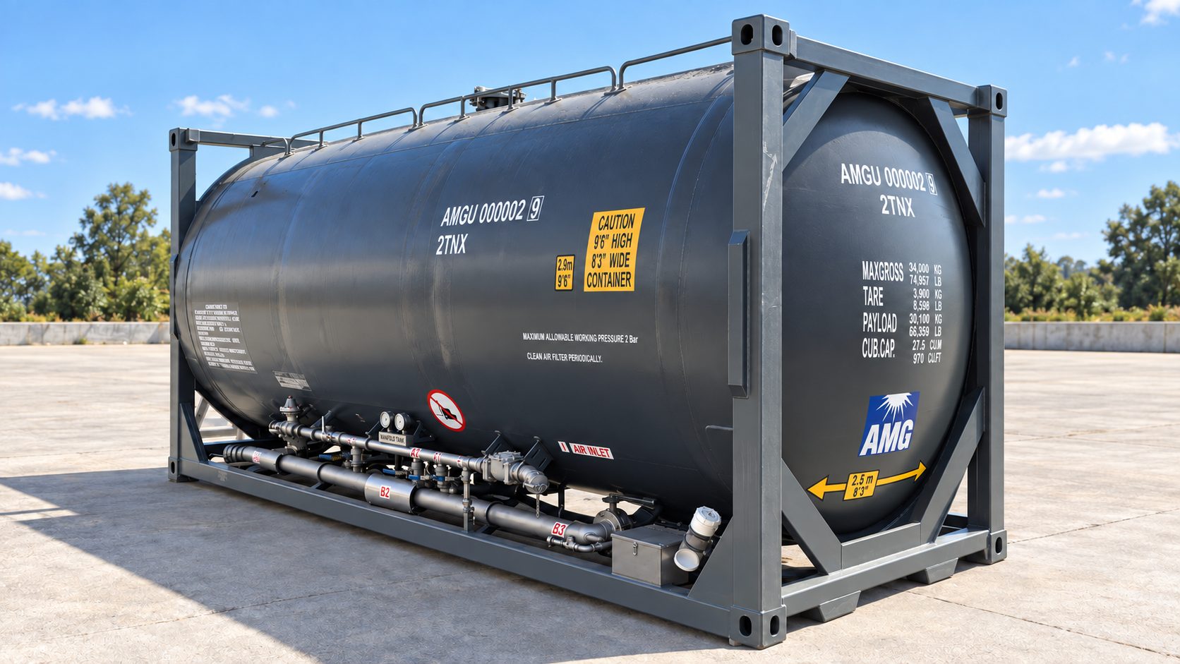
Pressure Tanker ISO
A 20ft ISO pressure tank container for bulk cement and dry bulk powder — built for performance, designed for reliability and engineered for peace of mind.
Explore the Pressure Tanker ISO in 3D
Skip tour-
01 · Overview
Every part, engineered.
Scroll to take it apart, piece by piece, and see how each system works.Each major part of the unit, explained chapter by chapter.
- 20ft ISO format
- 27.5 m³ capacity
- 30,100 kg payload
- 2 bar MAWP
-
02 · The ISO frame
Move it anywhere.
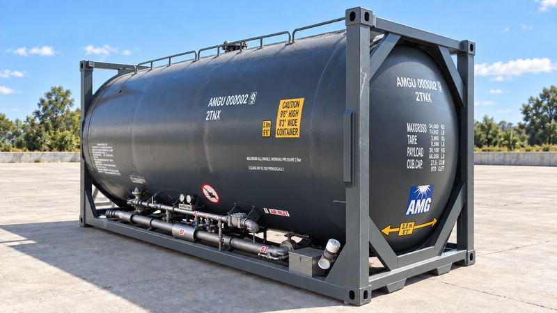
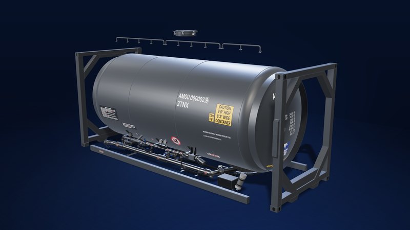
A standard 20ft ISO frame, 6,058 mm long, makes the unit globally compatible. Corner castings at all eight corners are the standard ISO fittings used to lift and secure it, and octagonal end frames cradle each end of the vessel.
- 20ft ISO · global format
- 6,058 mm long
- 2.9 m (9'6") high
- 2.5 m (8'3") wide
-
03 · The pressure vessel
Built light to carry more.
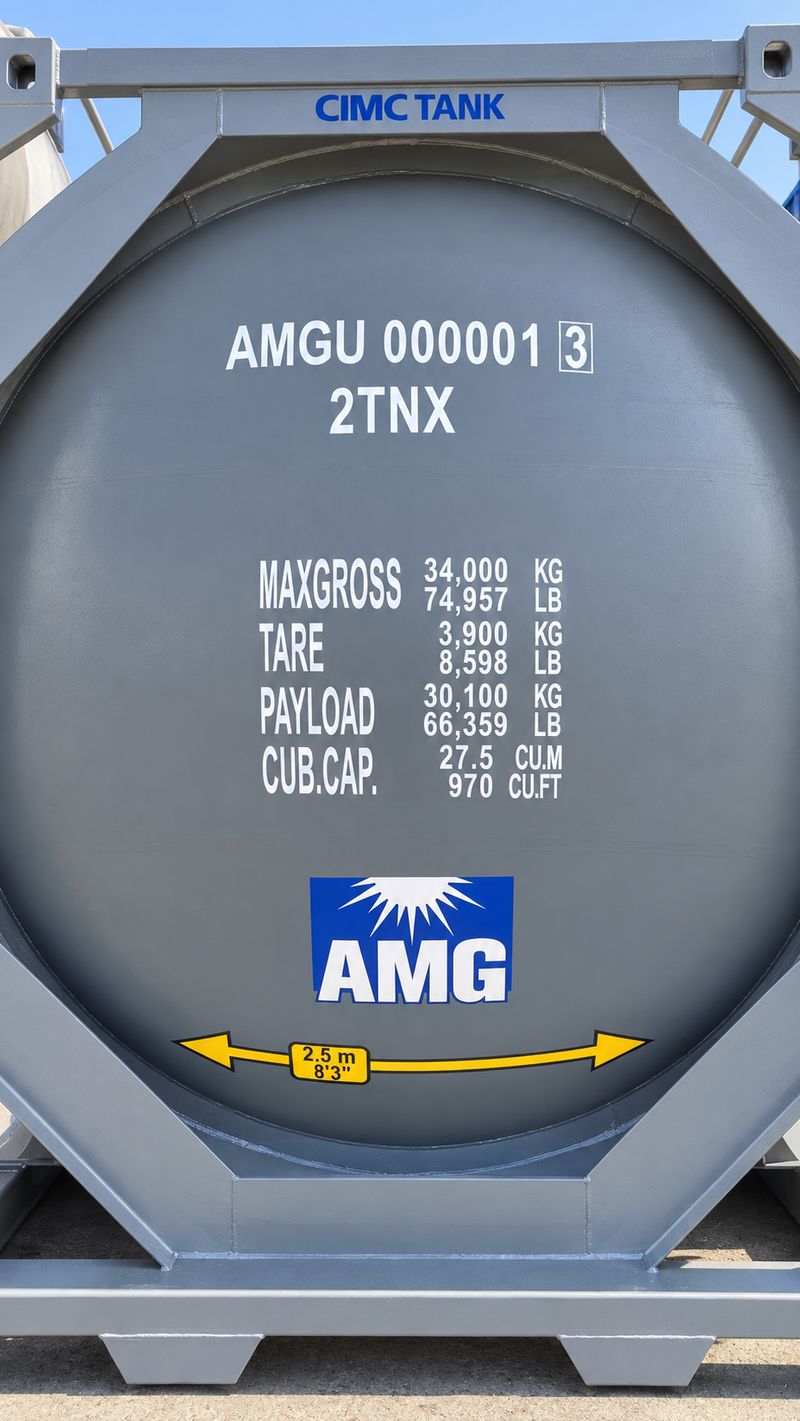
A 27.5 m³ pressure vessel, marked for a maximum allowable working pressure of 2 bar. At approximately 3,900 kg tare, it is optimised for payload: 30,100 kg within a 34,000 kg maximum gross mass.
- 27.5 m³ · 970 cu ft
- 2 bar MAWP
- 30,100 kg payload
- ~3,900 kg tare
-
04 · Inside
Shaped for clean-out.
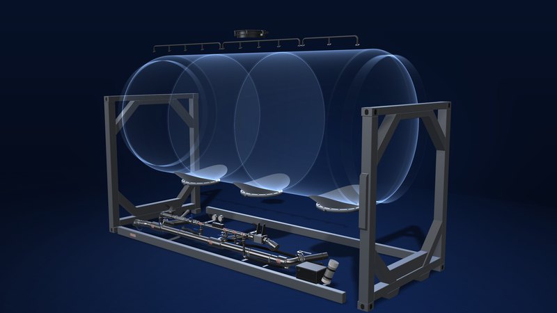
The vessel is divided into three compartments, each discharging through its own central discharge cone. Compartment geometry directs product naturally towards the cones, for maximum clean-out and minimal residual product.
- 3 compartments
- 3 central discharge cones
- Minimal residual product
Internal parts are shown schematically.
-
05 · Air-mat aeration
Aerated inside. Serviced outside.
Internal air mats deliver consistent, even product flow across all three compartments for faster unloading. Large removable bottom access flanges give external access to the mats, so maintenance needs no confined space entry.
- Internal air mats
- No confined space entry
- Removable base sections
- No external cup aerators
Internal parts are shown schematically.
-
06 · Air manifold
Air, finely controlled.
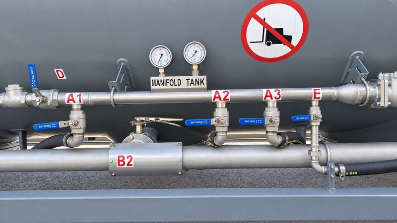
Air joint I, marked AIR INLET, feeds one manifold of ball valves: D, the air inlet valve; A1–A3, one aeration valve per compartment; and E, the boost valve. Dual gauges show manifold and tank pressure, helping operators spot blockages or abnormal pressure differentials.
- Ball-valve air control
- Dual pressure gauges
- Off-the-shelf fittings
-
07 · Discharge line
One compartment at a time.
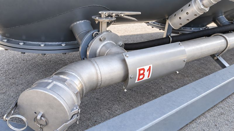
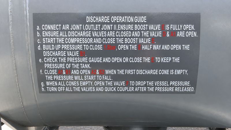
Each compartment has its own product line and butterfly isolation valve, B1–B3, feeding a common line to outlet joint II. Following the on-tank guide, B1 opens once pressure is close to 1.8 bar, and the compartments then discharge one at a time.
- B1–B3 butterfly valves
- Independent compartment control
- II · outlet joint
-
08 · Safety
Safety, in plain sight.
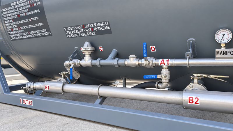
Safety valve C is marked BLOWER USE ONLY, and the decal above it sets out the response: if safety valve C opens, manually open air relief valve F to release pressure if necessary. Red-on-white letter labels beside the valves and joints match the on-tank instructions.
- C · Safety valve
- Blower use only
- Lettered valves
- 2 bar MAWP
-
09 · Storage & documents
Everything in its place.
A lockable toolbox, mounted on the frame, keeps operational spares and equipment with the unit. A dedicated document holder keeps compliance certificates separate from day-to-day paperwork.
- Lockable toolbox
- Dedicated document holder
- Certificates kept separate
-
10 · Markings & compliance
Fully compliant. Clearly marked.
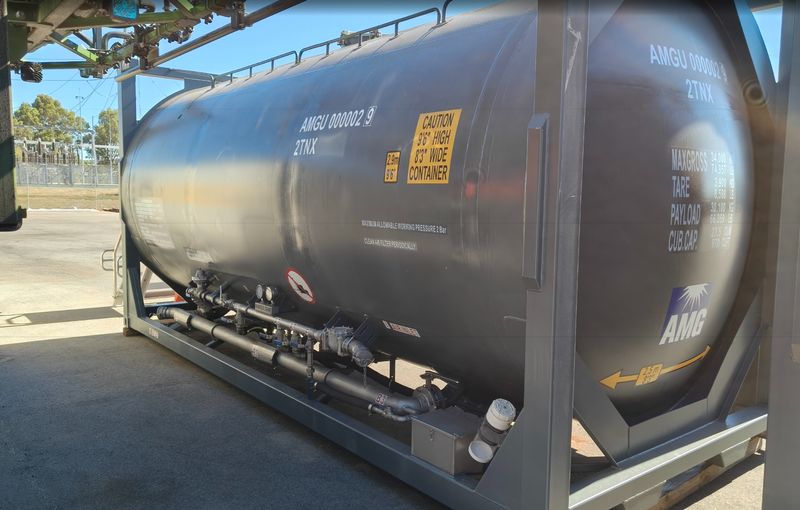
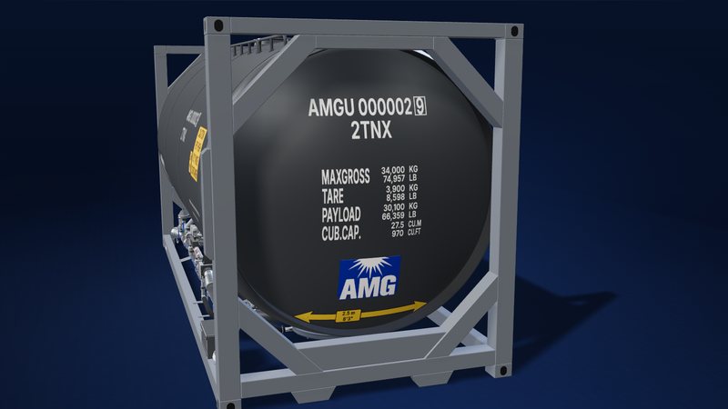
The dished end carries the unit's identity, AMGU 000002 9 · 2TNX, and its ratings: max gross 34,000 kg, tare 3,900 kg, payload 30,100 kg and capacity 27.5 m³. The unit is supplied with a full certification package.
- WorkSafe design registration
- WorkSafe plant registration (WA)
- PRV · inspection · CSC
- 20ft ISO format
-
11 · Summary
Move more. Cleaner. Safer. Smarter.
A simple, intuitive layout with minimal moving parts, designed for operators to use confidently. Built for performance, designed for reliability, engineered for peace of mind.
- Faster unload times
- Lower maintenance costs
- Maximum uptime
Parts indexEvery part of the 3D model, explained
02 · The ISO frame
- End frame · inlet end
- Octagonal end frame at the air-inlet end of the 20ft ISO frame. It cradles the dished end of the vessel between two corner posts.
- End frame · outlet end
- Octagonal end frame at the outlet end of the 20ft ISO frame. It cradles the dished end of the vessel between two corner posts.
- Corner castings · inlet end
- The four corner castings at the inlet end: the standard ISO fittings used to lift and secure the container.
- Corner castings · outlet end
- The four corner castings at the outlet end: the standard ISO fittings used to lift and secure the container.
- Bottom side rail · manifold side
- Bottom rail joining the two end frames along the manifold side. It carries the II OUTLET marking.
- Bottom side rail · far side
- Bottom rail joining the two end frames along the far side of the unit.
- Post-mounted box
- A slim box mounted on the outside of the corner post at the inlet end.
03 · The pressure vessel
- Pressure vessel
- The cylindrical body of the 27.5 m³ pressure vessel, marked for a maximum allowable working pressure of 2 bar and finished in dark anthracite.
- Dished end · inlet end
- Dished end closing the vessel at the inlet end. It carries the unit identity, the mass and capacity markings, the AMG logo and the 2.5 m (8'3") width marking.
- Dished end · outlet end
- Dished end closing the vessel at the outlet end.
- End ring · inlet end
- Ring band where the inlet-end dished end meets the octagonal end frame.
- End ring · outlet end
- Ring band where the outlet-end dished end meets the octagonal end frame.
- Top fitting
- A round fitting on top of the vessel.
- Top rail
- A rail running along the top of the vessel on the manifold side.
04 · Inside
- Compartment division 1–2
- Division between compartments 1 and 2 of the three-compartment vessel (shown schematically).
- Compartment division 2–3
- Division between compartments 2 and 3 of the three-compartment vessel (shown schematically).
- Discharge cone 1
- Central discharge cone at the bottom of compartment 1, at the outlet end. Compartment geometry directs product towards it for maximum clean-out.
- Discharge cone 2
- Central discharge cone at the bottom of the middle compartment. Compartment geometry directs product towards it for maximum clean-out.
- Discharge cone 3
- Central discharge cone at the bottom of compartment 3, at the inlet end. Compartment geometry directs product towards it for maximum clean-out.
05 · Air-mat aeration
- Air mat · compartment 1
- Internal air mat for compartment 1. Air-mat aeration delivers consistent, even product flow (shown schematically).
- Air mat · compartment 2
- Internal air mat for compartment 2. Air-mat aeration delivers consistent, even product flow (shown schematically).
- Air mat · compartment 3
- Internal air mat for compartment 3. Air-mat aeration delivers consistent, even product flow (shown schematically).
- Bottom access flange · cone 1
- Large, bolted, removable flange under discharge cone 1. It gives external access to the internal air mat, with no confined space entry.
- Bottom access flange · cone 2
- Large, bolted, removable flange under discharge cone 2. It gives external access to the internal air mat, with no confined space entry.
- Bottom access flange · cone 3
- Large, bolted, removable flange under discharge cone 3. It gives external access to the internal air mat, with no confined space entry.
- Aeration air hoses
- Flexible hoses running down from aeration valves A1, A2 and A3 towards the base of the vessel.
06 · Air manifold
- Air manifold
- Main air line along the manifold side. It carries air inlet valve D, aeration valves A1–A3 and boost valve E, each identified by a red-on-white letter.
- Dual pressure gauges
- Two gauges on a MANIFOLD TANK plate show manifold pressure and tank pressure side by side, for real-time visibility of operating conditions.
- Aeration valve A1
- Ball valve for aeration air to compartment 1. The operation guide has it open, with valve D, before the compressor starts.
- Aeration valve A2
- Ball valve for aeration air to compartment 2. The operation guide opens A2 and B2 once the first discharge cone is empty.
- Aeration valve A3
- Ball valve for aeration air to compartment 3.
- Air inlet valve D
- Ball valve on the air manifold. The operation guide has it open, with A1, before the compressor starts.
- Boost valve E
- Ball valve that the operation guide has fully open at connection, then closed to build pressure. During discharge it is opened or closed to keep tank pressure.
- In-line fitting
- An in-line fitting on the air manifold, beside air inlet valve D.
- Lateral fitting
- A fitting with an angled branch on the air manifold, between safety valve C and the in-line fitting.
- Air inlet housing
- Square-flanged housing on the air line beside air joint I. The stencil on the tank reads CLEAN AIR FILTER PERIODICALLY.
- Air joint I
- The air connection, marked I AIR INLET, with a capped quick coupling.
07 · Discharge line
- Product discharge line
- The product line running along the manifold side to outlet joint II.
- Discharge valve B1
- Industry-standard butterfly valve isolating compartment 1. It is the first discharge valve opened in the operation guide.
- Discharge valve B2
- Industry-standard butterfly valve isolating compartment 2. It opens, with A2, once the first discharge cone is empty.
- Discharge valve B3
- Industry-standard butterfly valve isolating compartment 3.
- Outlet joint II
- The product outlet, marked II OUTLET on the side rail, with a capped quick coupling.
08 · Safety
- Safety valve C
- Safety valve on the air manifold, marked BLOWER USE ONLY. If it opens, the on-tank decal instructs operators to manually open air relief valve F to release pressure if necessary.
- Vent valve & diffuser
- A ball valve with a perforated diffuser at the outlet end of the air manifold.
09 · Storage & documents
- Lockable toolbox
- Lockable toolbox mounted on the frame at the inlet end, for operational spares and equipment.
- Document holder
- A dedicated capped tube for compliance certificates, kept separate from day-to-day paperwork.
10 · Markings & compliance
- Side markings
- The manifold-side markings: unit AMGU 000002 9 · 2TNX, the 2.9 m (9'6") and CAUTION 9'6" HIGH 8'3" WIDE CONTAINER plates, the 2 bar working-pressure and air-filter stencils, the discharge operation guide and the safety decal.
20ft ISO pressure tank container
The Pressure Tanker ISO is a 20ft ISO pressure tank container for moving bulk cement and other dry bulk powders. Its three compartments each discharge through a central cone, while internal air-mat aeration delivers consistent, even product flow for efficient, reliable unloading.
A simplified design eliminates external cup aerators and their associated hoses and fittings, and industry-standard, off-the-shelf components keep spare parts simple. Large removable bottom access flanges allow the internal air mats to be maintained without confined space entry, and the tanker is supplied with a full certification package.
Key features
- 20ft ISO container format, globally compatible
- Three compartments with central discharge cones
- Internal air-mat aeration for even product flow
- Ball-valve air control and butterfly product valves
- Dual pressure gauges for tank and manifold pressure
- No confined space entry for air-mat maintenance
- Lockable toolbox and dedicated document holder
- WorkSafe design and plant registration (WA)
20ft ISO
Globally compatible format
Three compartments
Each with a central discharge cone
2 bar
Maximum allowable working pressure
Key specifications
- Max gross mass
- 34,000 kg
- Tare (approx.)
- 3,900 kg
- Payload
- 30,100 kg
- Capacity
- 27.5 m³
- Max. allowable working pressure
- 2 bar
Standards & compliance
Specifications
| General | |
|---|---|
| Product carried | Bulk cement and dry bulk powder |
| Container format | 20ft ISO tank container Globally compatible |
| Height | 2.9 m Marked 9′6″ high container |
| Width | 2.5 m Marked 8′3″ wide container |
| Masses & capacity | |
| Max gross mass | 34,000 kg 74,957 lb |
| Tare | Approx. 3,900 kg 8,598 lb |
| Payload | 30,100 kg 66,359 lb |
| Capacity | 27.5 m³ 970 cu ft |
| Pressure, aeration & discharge | |
| Maximum allowable working pressure | 2 bar |
| Compartments | Three, each discharging through a central discharge cone |
| Aeration | Internal air mats with ball-valve air control |
| Aeration air valves | A1–A3 Ball valves for precise airflow control |
| Discharge (product) valves | B1–B3 Industry-standard butterfly valves |
| Air system valves | C safety valve (blower use only) · D air inlet · E boost · F air relief |
| Joints | I air joint · II outlet joint |
| Instrumentation | Dual pressure gauges Tank pressure and manifold pressure |
| Maintenance, storage & documentation | |
| Maintenance access | Large removable bottom access flanges and removable compartment base sections |
| Toolbox | Lockable, for operational spares and equipment |
| Document holder | Dedicated holder for compliance certificates |
| Compliance | |
| Registration | WorkSafe design registration · WorkSafe plant registration (WA) |
| Certification | Supplied with a full certification package PRV, inspection, CSC and more |
Masses, capacity, dimensions and working pressure are taken from the tank’s data plate and markings.
The approx. 3,900 kg tare weight is optimised to maximise payload capacity, and further reductions are achievable for bulk production builds.
Built for performance. Designed for reliability.
Thirteen practical advantages — from faster, cleaner unloading to safer maintenance and full compliance — engineered for peace of mind.
-
Efficient, reliable unloading system
Internal air-mat aeration delivers consistent, even product flow across all compartments, improving discharge efficiency and reducing unload times.
-
Simplified design, greater reliability
Eliminates external cup aerators and their associated hoses and fittings, reducing common failure points and ongoing maintenance issues.
-
Optimised internal flow design
Compartment geometry directs product naturally towards the central discharge cones, ensuring maximum clean-out and minimal residual product.
-
Independent compartment control
Each compartment is fitted with its own product line and isolation valve, allowing controlled, flexible discharge operations.
A1–A3 aerationB1–B3 discharge -
Standardised, easily replaceable components
Industry-standard, off-the-shelf components minimise downtime and simplify spare parts management.
- Product valves
- Butterfly valves
- Air control
- Ball valves
- Boost valves & fittings
- Off-the-shelf
-
No confined space entry for maintenance
Large removable bottom access flanges allow external access to the internal air mats, eliminating the need for confined space entry during maintenance.
-
Faster maintenance & cleaning
Removable compartment base sections enable easy access for air-mat replacement, internal cleaning and clearing stubborn blockages.
-
Improved operational diagnostics
Dual pressure gauges (tank pressure and manifold pressure) provide real-time visibility of operating conditions, helping operators quickly identify blockages, airflow issues or abnormal pressure differentials.
-
Enhanced airflow control
A ball-valve air system allows finer control of aeration, improving discharge performance and reducing the risk of bridging or inconsistent flow.
-
Lightweight design for maximum payload
Approx. 3,900 kg tare weight, optimised to maximise payload capacity.
Further reductions achievable for bulk production builds.
-
Fully compliant & certified
- 20ft ISO container format (globally compatible)
- WorkSafe design registration
- WorkSafe plant registration (WA)
- Supplied with a full certification package (PRV, inspection, CSC and more)
-
Integrated storage & documentation solutions
- Lockable toolbox for operational spares and equipment
- Dedicated document holder for compliance certificates, separated from day-to-day paperwork
-
Built for ease of use
A simple, intuitive layout with minimal moving parts, designed for operators to use confidently with reduced training requirements.
Controlled discharge, compartment by compartment
Internal air-mat aeration, ball-valve air control and dual pressure gauges give operators precise control of every unload.
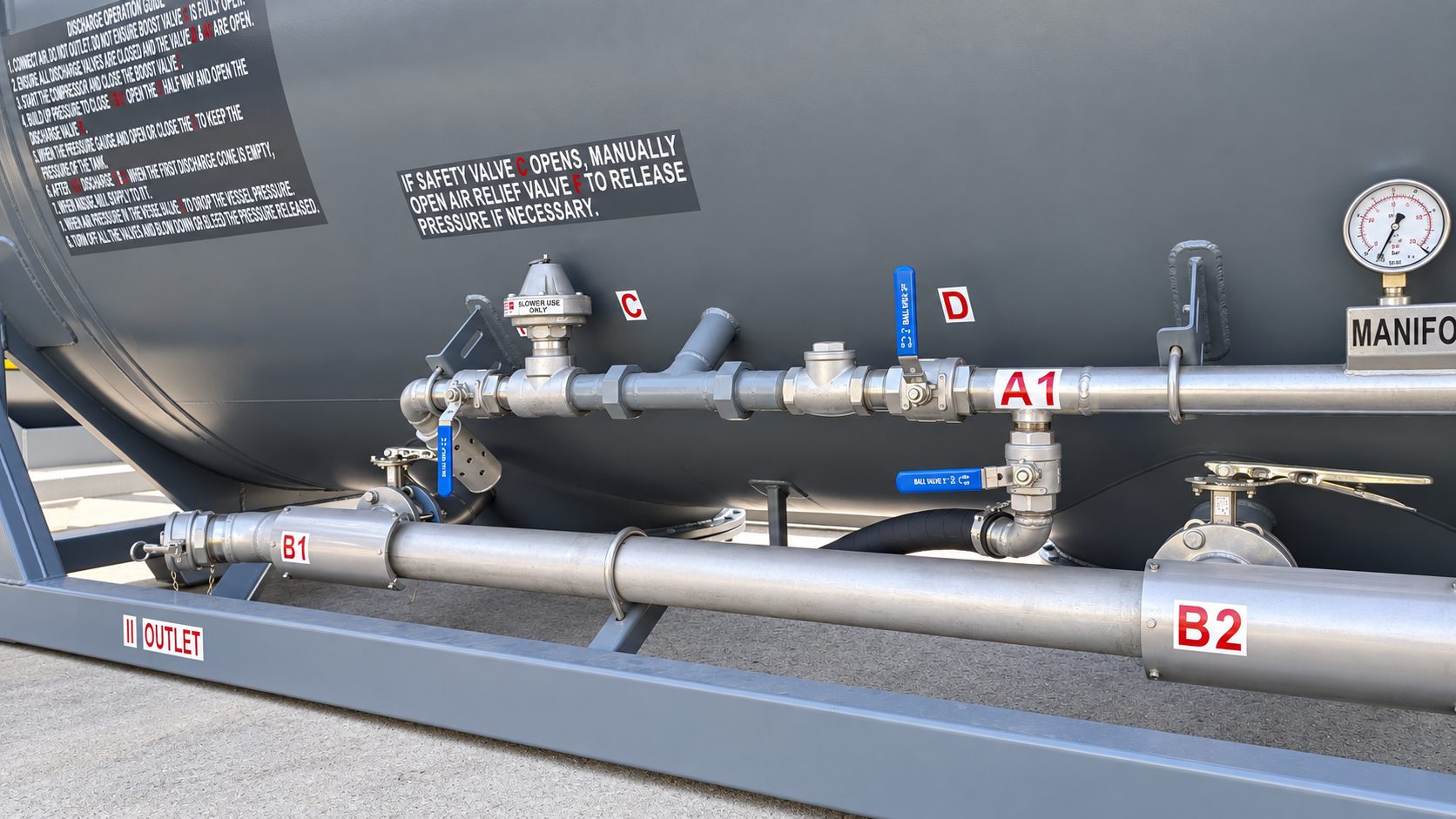 Safety valve C, air inlet D, A1 and outlet B1
Valve and joint codes at a glance
A quick reference for the valve and joint letter codes used in the discharge steps and safety note below.
- A1–A3
- Aeration air valves
- B1–B3
- Discharge (product) valves
- C
- Safety valveBlower use only
- D
- Air inlet valve
- E
- Boost valve
- F
- Air relief valve
- I
- Air joint
- II
- Outlet joint
Discharge in eight steps
Summarised from the Discharge Operation Guide decal fitted to the tank. Always follow the on-tank decal and site procedures.
Connect
Connect air joint I and outlet joint II; ensure boost valve E is fully open.
Set the valves
Ensure all discharge valves are closed and valves D and A1 are open.
Start the compressor
Start the compressor and close boost valve E.
Build pressure and discharge
Build pressure to close to 1.8 bar, open E halfway and open discharge valve B1.
Monitor tank pressure
Monitor the pressure gauge and open or close E to maintain tank pressure.
Move to the next compartment
When the first discharge cone is empty (pressure starts to fall), close A1 & B1 and open A2 & B2, then continue through each compartment.
Release vessel pressure
When all cones are empty, open valve F to drop the vessel pressure.
Shut down
After the pressure is released, turn off all valves and the quick coupler.
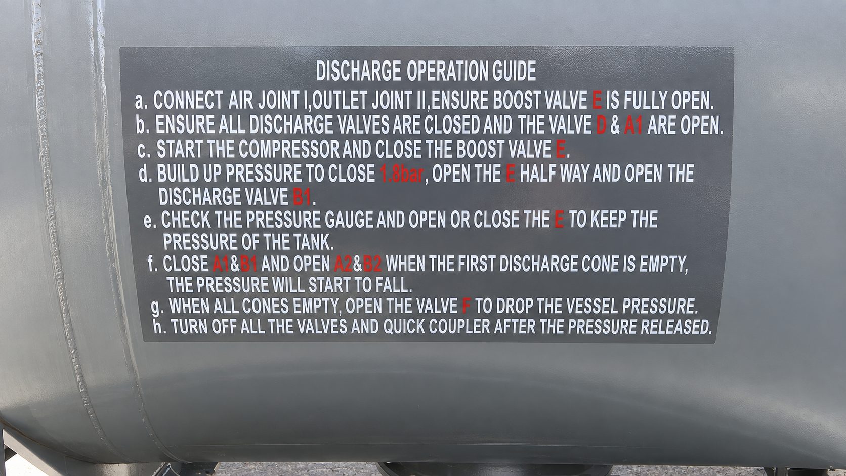 Discharge Operation Guide decal
If safety valve C opens, manually open air relief valve F to release pressure if necessary.
Operators must always follow the on-tank decal and site procedures. These steps are a summary only.
Move more. Cleaner, safer, smarter.
What the Pressure Tanker ISO delivers for your bulk cement operation.
~3,900 kg tare weight
Optimised for maximum payload
Faster unload times
Consistent flow, greater efficiency
Lower maintenance costs
Simplified design, fewer failure points
Maximum uptime, minimum downtime
Built tough, built smart
20ft ISO global compatibility
Move it anywhere, operate everywhere
A closer look at the Pressure Tanker ISO
Select any photo to view it full size.
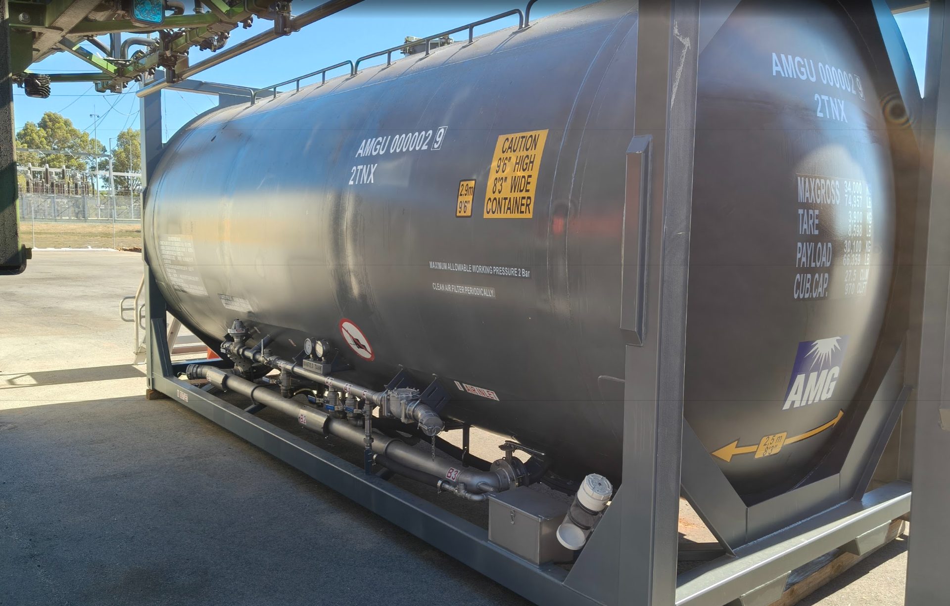 In service at a WA siteUnder a loading gantry
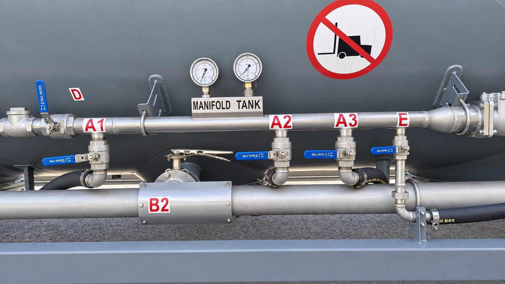 Manifold & dual pressure gaugesTank and manifold pressure at a glance
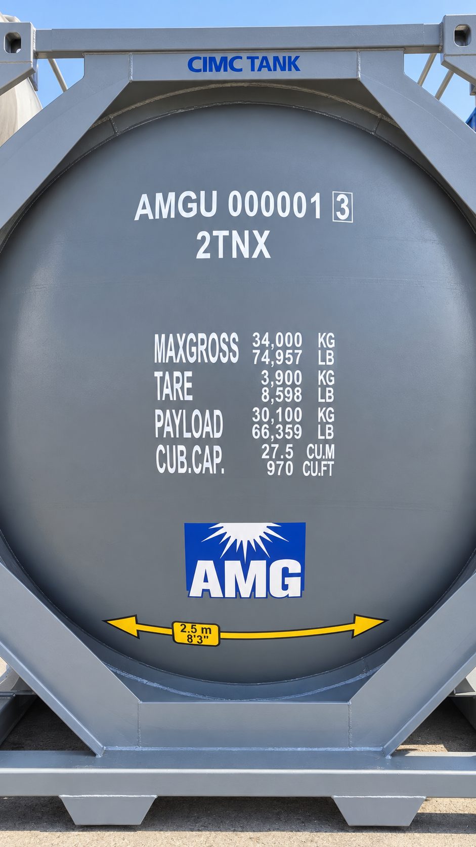 End face & data plateMax gross, tare, payload and capacity
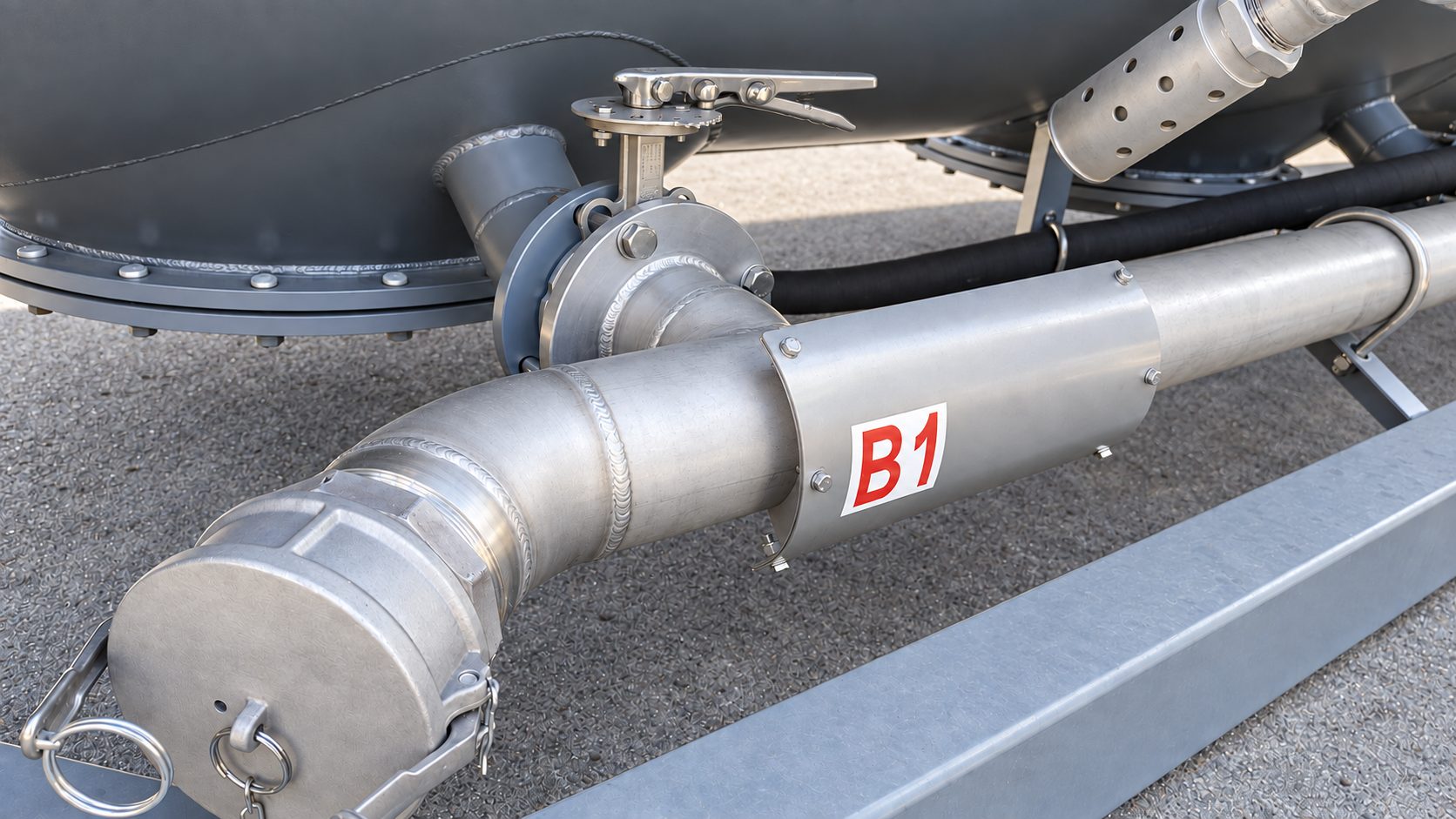 B1 discharge outletButterfly valve, camlock cap and bolted flange
Discharge operation guideStep-by-step decal on the tank side
Valve assemblySafety valve C, air inlet D, aeration valve A1 and outlet B1
B1 discharge outletButterfly valve, camlock cap and bolted flange
Discharge operation guideStep-by-step decal on the tank side
Valve assemblySafety valve C, air inlet D, aeration valve A1 and outlet B1
Ready to move more cement?
Talk to our Perth-based team about the Pressure Tanker ISO and your bulk cement requirements, or request a quote today.